The AX10410 is an analog/digital I/O card for the PC104 bus as present on the PCM-5862. It features 8 differential or 16 single-ended analog inputs with 12-bit resolution, signal levels of +10V, +5V, +2.5V, +1.25V unipolar and ±10V, ±5V, ±2.5V, ±1.25V bipolar. It also provides 2 analog outputs for 0~10V (unipolair) or -5~5V (bipolar), 8 bit digital input and 8 bit digital output.
I set the jumpers and switches to:
| S1 | 1-Off 2-Off 3-On 4-On 5-On 6-Off |
0x310-0x31F I/O Port range | |
| SW1 | Away | Unipolar input mode | Away means away from the PC104 connector Toward means toward the PC104 connector |
| SW2 | Away | Unipolar output mode | |
| SW3 | Away | Unipolar output mode | |
| SW4 | Toward | Single ended operation | |
| JP1 | Not used | ||
| JP2 | 1-2 | Unipolar input mode | |
| JP3 | 1-2 | Single ended operation | |
| JP4 | 2-3 | DRQ3 used for DMA | |
| JP5 | 2-3 | DRQ3 used for DMA | |
| JP6 | 2-3 | Internal 100 kHz clock used for counter 0 | |
| JP7 | 1-2 | 1 MHz clock used for ADC timer |
A big problem is the 50 pin connector for the in- and outputs. This connector is open to the side and with a flat cable connector inserted, it is too wide. It touches the Pentium cooler and the whole AX10410 board is turned with respect to the PC104 connector on the motherboard. Therefore Ron van Puffelen replaced this connector with a connector which is open to the top. Now a flat cable connector can easily fit, without touching anything. These foto's show the new situation:
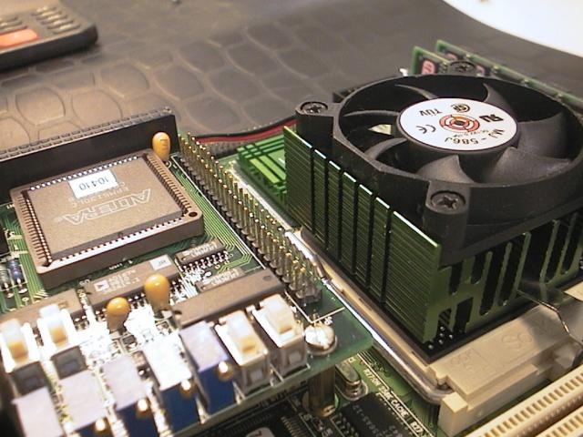 |
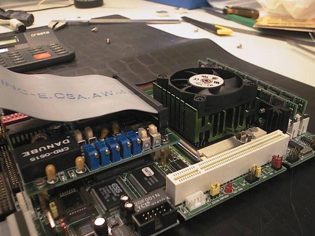 |