Edwin Steffens designed and built a PCB with some DC/DC converters to supply all voltages needed by the Pentium motherboard and the peripherals like the camera, the wireless ethernet etc. He also gave us the high power 24 to 5 volt converter which must be installed under the Nomads power supply PCB. Because Edwins PCB needs this 5 volt we installed the high power converter first. Edwins PCB was manufactured using a LPKF fraise with very thin traces and caused al lot of voltage drop in the 5 V line, so Ron van Puffelen designed a real PCB. We mounted this new PCB on the computer carrier, and we describe how to install this PCB in "Mounting the Computer".
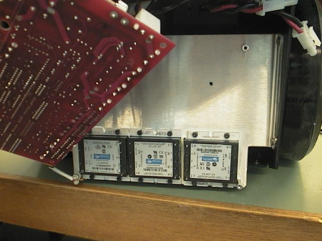
The first step was to open the Nomad front cover. It is fixed with 8 hex (inbus) screws. The front cover is connected to the power supply PCB by two cables. After disconnecting these, the front cover was put aside. After removing the front cover the aluminum PCB carrier was loosened by removing the two hex screws on either side of the Nomad. Now all power connectors on the PCB were disconnected, the low power connectors from the sensors etc. didn't need disconnecting. (Tip: mark the connectors to prevent mixing them when reinstalling the PCB!) Finally the four screws on the corners of the PCB and the two screws on the top left were removed. (These two screws fix the power amplifiers to the heatsink.) Now the PCB was carefully removed, making the power converters accessible.
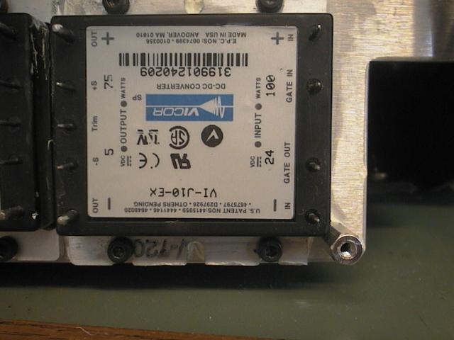
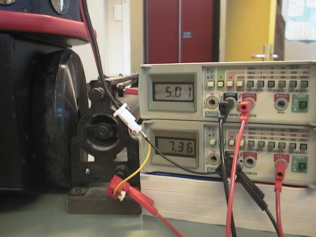
The DC/DC converter had to be installed on the free (rightmost) place, but the bottom right spacer blocked the heatsink. Therefore we removed a part of the heatsink. We coated the heatsink in thermal compound. We used 4 hex screws to fix the converter, but we didn't tighten them yet. The converter had to be mounted up-side-down to match the sockets in the PCB. We reinstalled the PCB, with some difficulty because all pins from the converters had to fit in their sockets. After we fixed the PCB with the four screws on the corners, we tightened the hex screws holding the new converter. Finally we replaced all other screws, connectors etc. and tested the voltage on J13 (5.25V). We also performed a load test (5.01V @ 7.36A).
 |
 |
 |
| The power converters | Note: Upside down! | Power for the Pentium |