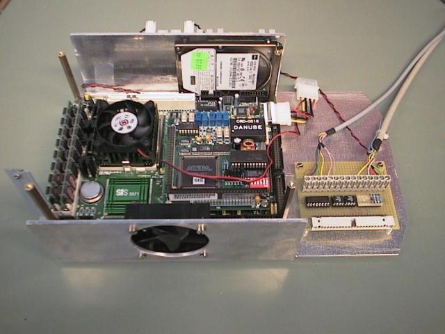
The computer and all peripherals should be mounted under (hanging from) the top lid of the Nomad. Although in a original SuperScout the Pentium board is mounted upside down, for us it was easier and more secure to mount it in normal position. Daan Noteboom (our mechanic) made a aluminum carrier on wich we stacked the Pentium board, the AX10410 I/O card and the WinTV card. For the WinTV card we used a PCI extender/converter, so the card is parallel to the Pentium board. This gives a compact construction, but the airflow for cooling might be blocked easily and care had to be taken to keep the airflow free. Because the WinTV card is on top, there is enough space to replace with an IMAP vision processor. On the side of the carrier we mounted the hard disk and Edwin's converter PCB. Using long spacers, we mounted the carrier under the lid.
Later we modified the carrier in cooperation with Wim van Oel. The main enhancements were the mounting of a ventilator for cooling and extension of the carrier bottom. On this extension we mounted the interface/buffer print from Ron van Puffelen.
 |
 |
 |
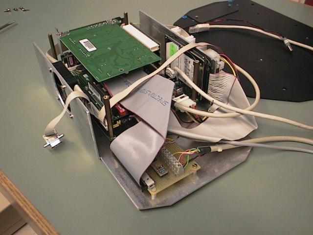
We made new cables for Ethernet, keyboard, monitor and COM1/COM2, because the originals which came with the PCM-5862 were too short. The original ethernet cable ends in a RJ-45 socket, but we made a cable ending in a plug, so it fits immediately in the BreezeNET wireless ethernet adapter. The keyboard connector on the PCM-5862 is a special, 8 pin, single-row type, which was not easily available. Therefore we used a 16 pin double-row Berg connector, which pervents damages when inserted wrongly.
| Ethernet | PCM-5862 CN11 |
RJ-45 (clip up) |
|
| 3 4 9 10 |
3 6 1 2 |
||
| Keyboard | PCM-5862 CN15 |
Alternative Berg |
5p female 180º DIN |
| 5 6 7 8 |
9 11 13 15 |
4 5 2 1 |
|
| Monitor | PCM-5862 CN1 |
15p female D type |
|
| Serial | PCM-5862 CN16 |
9p male D type |
|
| 1 - 9 11 -19 |
COM1 1 - 9 COM2 1 - 9 |
||
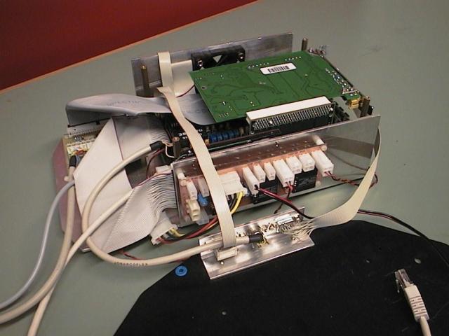
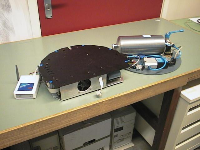
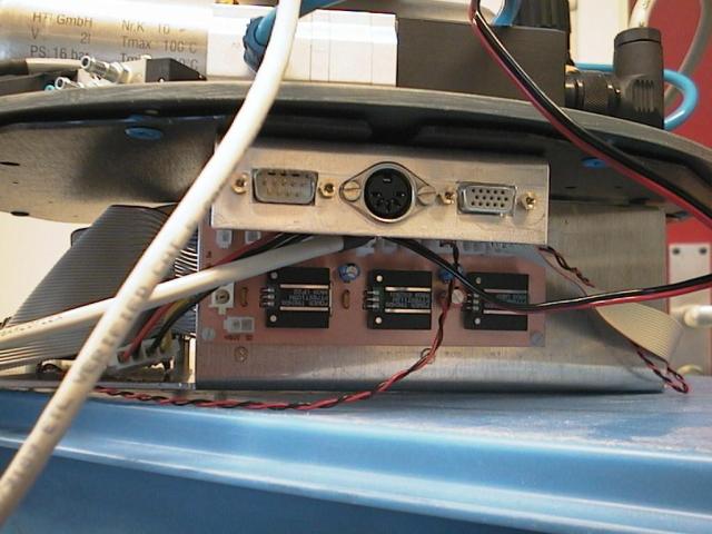
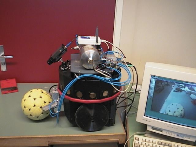
Two cables were connected between the interface/buffer print and the pneumatic devices, using screw terminals. The video connector, the keyboard connector, and the COM1 serial port connector were fixed in a small piece of aluminum, mounted at the back under the Nomad lid. The cable for COM2 was plugged in the Host port in the Nomad lid. (That is, it was not plugged directly into the Nomad controller board.) The Nomad lid was fixed on top of the carrier, and on top of that we mounted the pneumatic devices. This construction was mounted on the Nomad, using 35 mm spacers. We used long 3 mm bolts which we inserted from the inside of the Nomad, through the rim, pointing up. Now the lid can be removed while the spacers will remain in place, without falling into the Nomad. On the front of the Nomad we mounted the camera.
 |
 |
 |
Edwin's converter PCB is only connected to the 24 V on the Nomad power supply. The PCB has a connector for the 5 V too, but this causes too much voltage drop. We connected the 5 V on the power supply directly to the Pentium, taking only the +12 from the convertor PCB. We inserted a DPST switch in the 24 V and 5 V cables, so we can start the Nomad without the Pentium. This is necessary because the Pentium take so much power, there isn't anything left to charge the batteries. Ron modified the PCB to supply 24 V on the free pin of the ±12 V connectors. We used 3 ±12/24 V connectors: 1 for the ventilators (24 V/12 V), 1 for the interface/buffer print (24 V) and one for the camera (12 V). We used 1 regulated 5 V connector, for the BreezeCOM (Edwin's PCB contains a 24 V to 5 V converter for the BreezeCOM).
The whole construction was designed to give relatively quick access to the computer and leave the possibility to remove the whole computer and use for example a laptop. The pneumatic pipes are still a problem, they use screw connections, but we're working on that too.